| Reproducing stressed skin effect in aircraft models |
You
probably already had the opportunity to see models showing the so
called "stressed skin" panel effect. It is a very interesting effect
which adds a lot of realism to your model, as the effect is present to
some extent in any aircraft. There are two or three variations of
methods to simulate stressed skin, but before entering into the
subject, let me start by saying that if there is something misnamed in plastic modeling, it is stressed skin. If it is to contain the word stress in it, the correct should be unstressed skin effect, at least for aircraft on the ground.
A bit of engineering
Take a look at those marvelous cutaway drawings:
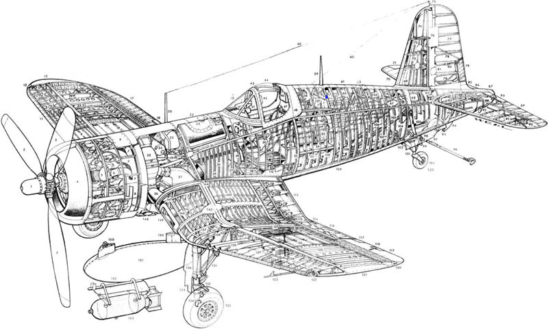
What they have in common? They are cramped with structural details. In order to understand what stressed skin is, let's start by talking about these structural details. As you know, any aircraft structure is essentially a skeleton covered by a skin (pretty much like those balsa wood models). The skeleton parts are generally spars, ribs and stringers. These structural elements provide strength against bending and tensile loads, but almost no resistence to shear. If one would use spars and ribs only, and still aim a shear strenght, the weight of the resulting design would be prohibitively large. That's where the skin comes into play.
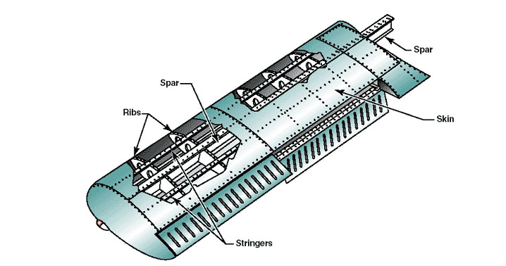
The skin is not only a thin metal sheet riveted along the ribs and stringers. It must be pre-stressed - or at least tightly fixed in place, which means that the riveting holes are calculated to be drilled along lines slightly smaller than the corresponding ones along the stringers and ribs. As a result, the skin must be somewhat stretched to fit its place. When you do this to all panels of a wing or fuselage, the skin is pre-stressed, just like a guitar string (or, in our balsa wood models, why we dope the skin - to make it tight). The result is a much more strong structure than the one which would be obtained if the skin wasn't pre-stressed. Not all panels in an aircraft are pre-stressed, but you can bet no panel is loosely fixed. Because it is so thin, without the pre-stress it will only add weight and no additional strentgh to the structures. So much so that fuselages don't have spars, they are only stringers, ribs and skin...
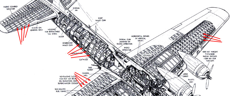
Therefore, the stringers, the ribs and occasionally the spars are the areas along which the skin panes are riveted. It is not difficult to identify them in an aircraft cut-a-way drawing. Check out this B-17 drawing. The arrows are showing areas that have rivet lines.
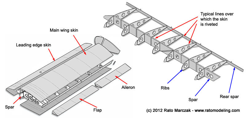
Now, what is the stressed skin effect, afterall? It is a representation on a scale model of the loosening of a skin panel due to use and loads. In order to unerstand it better, take a look of the wing center section drawing of a F4U Corsair, from the erection manual:
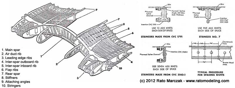
You can see several types of stringers (on the right) and the skin riveted to them. Here is a simpler version:
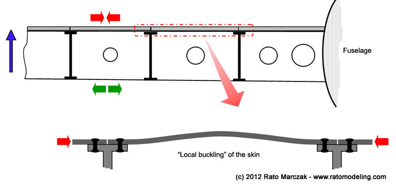
At this point it is important to understand that the wing (or any other structural part) sustain forces (lift, landings, manouvers) during operation. In the present case, bending is an example of forces acting on the structure. The lifting loads tend to bend the wing upwards. This produces a compression of the upper wing panels and a traction on the lower wing panels. Since the compression strength of the skin is minimal, it may buckle outwards, making a bubble on the area inside each panel lines perimeter (buckling is - stricktly speaking - not necessarily what happens here, so the term is used in a loose way):
The effect may happen with a few panels, or several consecutive panels. It all depends on each particular aircraft design. After the load is decreased to normal levels, it is expected that the skin will return to its flat shape. However, after hundreds of repetitive actions, small permanent deformations will occur, either on the skin, on the rivets, or on the surrounding structures, preventing the skin of returning to its original shape. Please understand that this is absolutely normal to some extent, and a buckled panel not necessarily means it failed. Do not confuse this with heavily deformed skin found on badly repaired areas, or heavily wrinkled panels found in restored (non flyable) warbirds which always tend to use the most possible original parts. It is also worth to note that manufacturing processes play an inportant role here, and many aircraft leave the factory already showing the effect. I mean, riveting process itself can (and generally do) produce the effect as the rivet lines pull the skin against the ribs and stringers, leaving sequences of bulges that is readily visible.
However, if the skin panel is no longer stretched as originally designed due to use (it has losen with time), then it is no more a pre-stressed structure as desired. That's why I mentioned that stressed skin is a bad name for it. I've seen modelers calling it quilted effect or oil canning effect. I'd rather prefer these names...
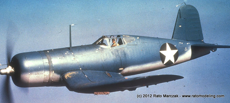
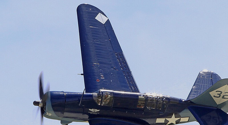
Here are some photos showing the effect on actual aircraft. The Corsair had a number of buckled panels on the area below the cockpit. This can be found in several wartime photos, like this one:
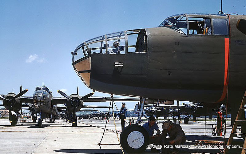
This B-25 is brand new at North American plant, yet the effect is visible under the cockpit:
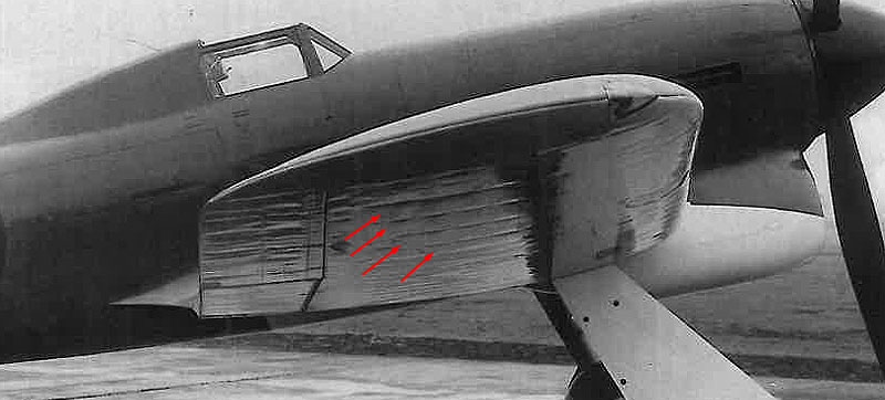
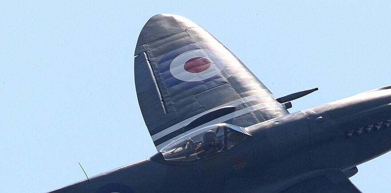
Another interesting example is the Typhoon prototype, with the riveting lines quite visible under the wing:
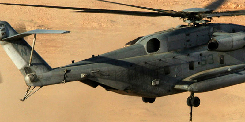
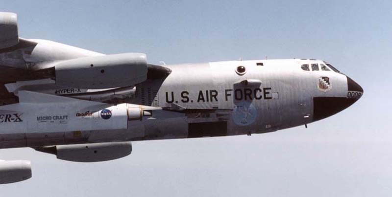
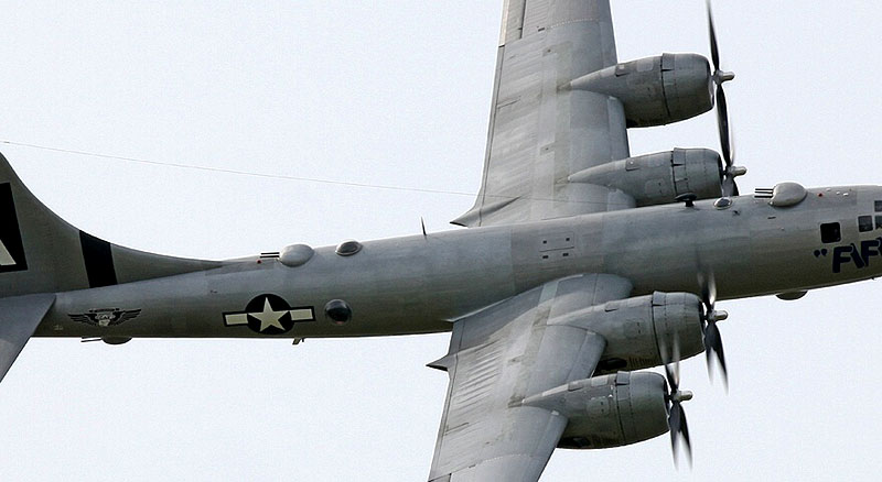
The Sea Stallion and the Stratofortress are two pathological examples of modern aircraft with buckled panels. The Sea Stallion show the effect on both fuselage sides adjacent to the rear ramp, while the early B-52s had the front fuselage full of sheared panels (look under the "air" of U.S. Air Force marking):
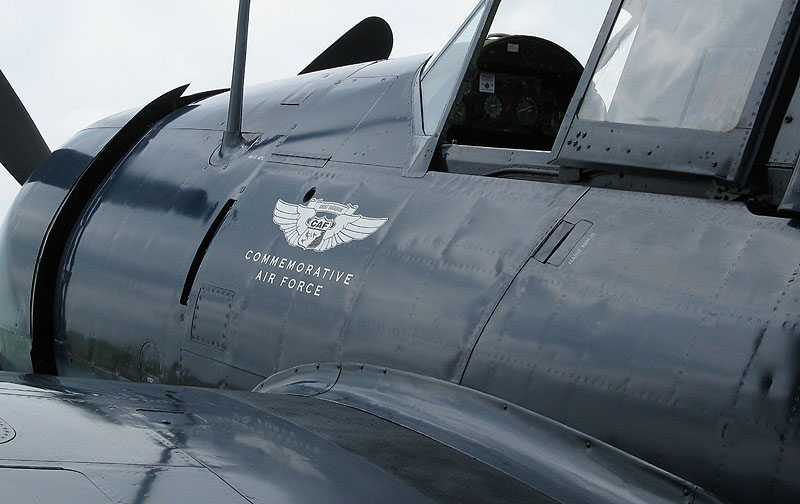
I don't like to use restored warbirds as examples, but if they are flyable, faulty panels would not be allowed, they are better illustrations of the effect than B&W wartiime photos:
There are other technicalities involved, but I won't enter in such details. You've got the picture.
Get ready
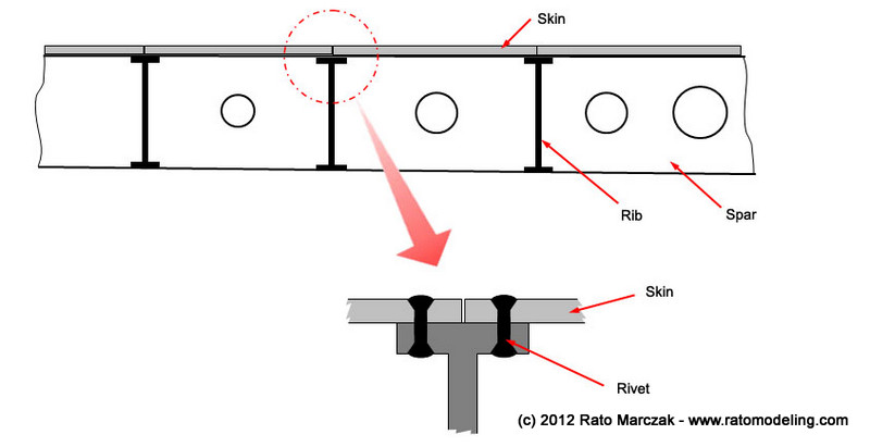
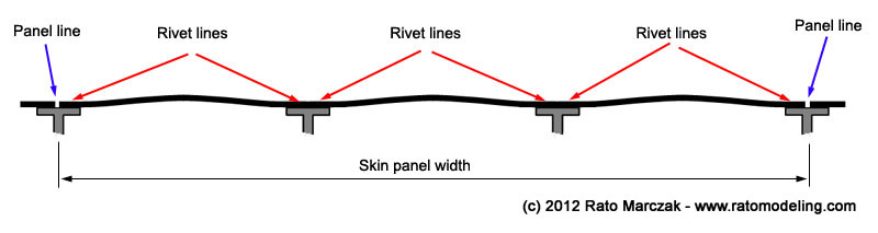
So, where to start reproducing the effect on your model? If you want a short path, the panel lines are certainly a good start, but you must remember that panel lines, as the name says, are the lines delimiting the perimeter of the skin panels. Along with them, there are several other rivet lines inside each skin panel. If we look at a cross section spanning several ribs, what you see is the following:
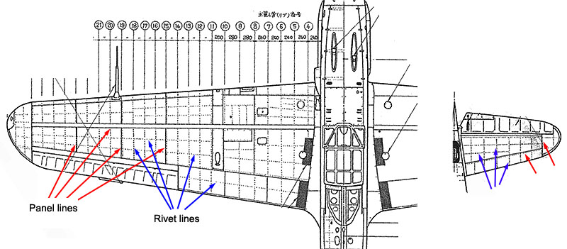
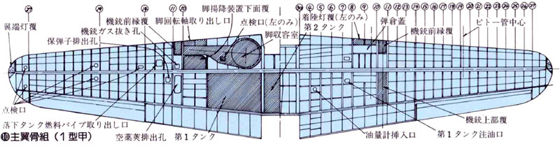
Therefore, to be accurate you will benefit of good quality drawings of you aircraft. These plans help you to know where the rivet lines should go, besides the panel lines. There are several publications (Kagero, Koku-fan, Model Art, Design with Precision, among others) known for publishing reliable engineering plans, and several others not so (watch out with those drawings where the rivets are merely decorative features added by the artist). Do your homework. Here are two examples I used for a 1/72 Kawasaki Ki-61 project:
Then you have basically two options to depict the effect on your model: (a) you may add material (dissolved putty, Mr.Surfacer and the likes) between the rivet lines, to make it bulged. The difficulty of this method is to sand the borders of the puttied area to make it blend flush with the plastic. This approach was used by some famous modelers, including master modeler Robert Karr on his 1/32 Blenheim:
The other option is (b) to remove material along the rivet lines to make the non-worked areas to stand slightly higher. This is the preferred method of most modelers, but it also has its disavantages. You loose the panel lines, which must be rescribed later, and may not be able to avoid damaging other surface details. This is the method preferred by several modelers, Brian Criner, Bill Cronk, Jaroslav Galler, among others. Here are a couple of photos showing their work with this method:
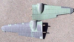
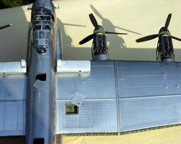
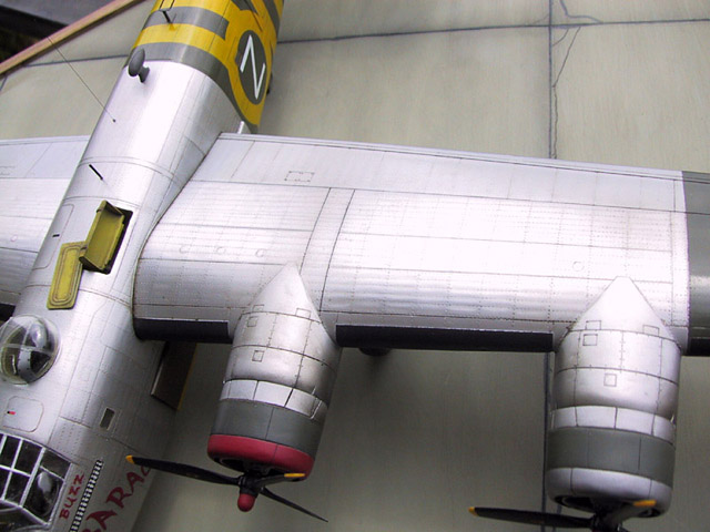
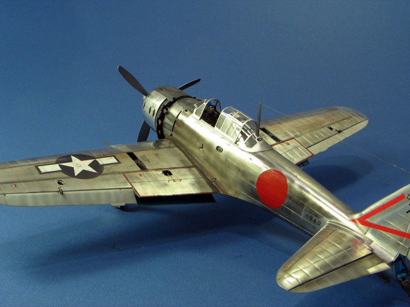
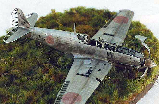
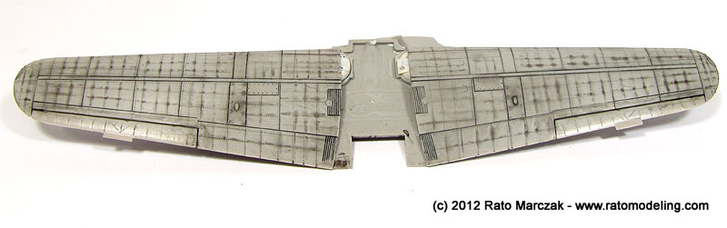
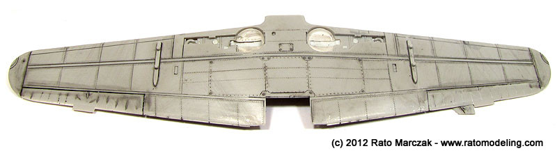
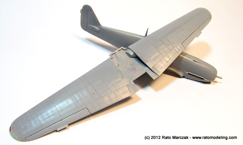
We are going to show the second approach on this article. The series of photos below show models from several modelers, and help to illustrate how the effect can add realism to a model, particularly the ones in natural metal finish:
Basic steps
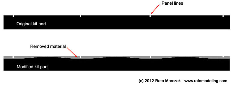
Now that you got here, let's put it simple: our aim is to produce more or less parallel waves over specific areas. As an example, lets remove material along panel lines molded in the original kit part::
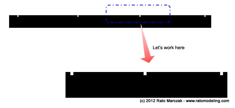
Note that the panel lines may disappear completely or partially, so that a rescribing job will be necessary at the end. To make thing simple (to me), I'll illustrate the basic steps to produce one deression along a panel line:
Start doing some research. You don't want (you shouldn't) to make the effect over the whole airframe. Study photos of the real thing. Select the areas which are more prone to show the effect and take notes, if possible with the aid of a reliable drawing. Once you're done, mark the areas to be worked using a pencil or a sharpie (watch out, clean it afterwards) over the parts:

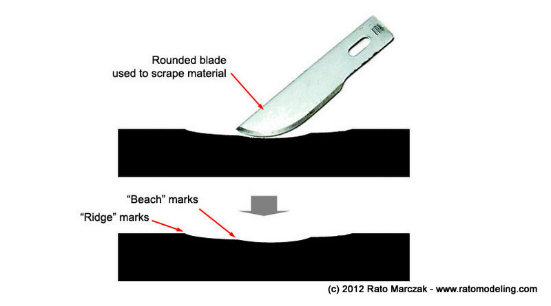
Once you stabilished where the depressions go, the first thing to do is to remove material quickly. In 1/48 or 1/32 scale, a curved hobby knife can be used as a srapper. It is important to be a curved tool, or you will produce risks difficult to remove later. Start lightly and then increase the force, but do not exaggerate - a few passes are enough.
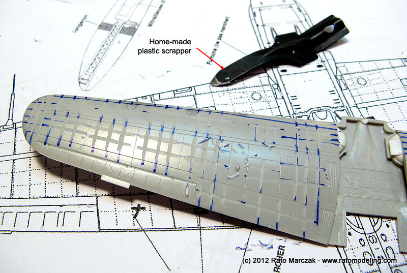
You certainly will develop your own feeling with practice. In some cases, special tools may work better. I have a plastic scrapper specially devided for this:
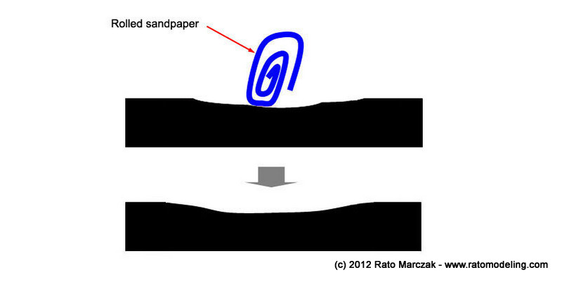
At this point you will feel that you just scrapped (no pum intended) your latest model. Don't give up. Next, papare pieces of sandpaper, tightly rolled to fit the scrap marks you just did. I recommed to start with a 400 grade and then move to a 600 grade. Sand the marks with the rolls aligned to them. The objective of this step is to remove the steps (another unintentional pum) left by your scrapper - the ridge and beach marks highlighted in the figure above.
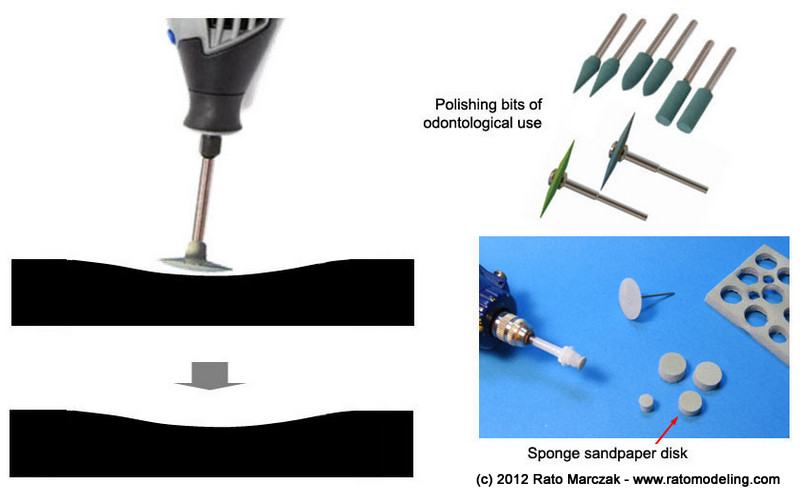
The rolled sandpaper will not enter into the smallest risks. In order to improve the smoothing, you can use an abrasive rubber dental bit. This is used by dentists to polish dental prothesis. Look for it, there are several types and brands on the market and they are useful for many tasks in modeling. Alternatively, you can punch out disks of 800 grade sandpaper and adapt them to your rotary tool. I like to use those sponge backed sandpapers for that, but you still can do it manually, but it takes a long, boring time...
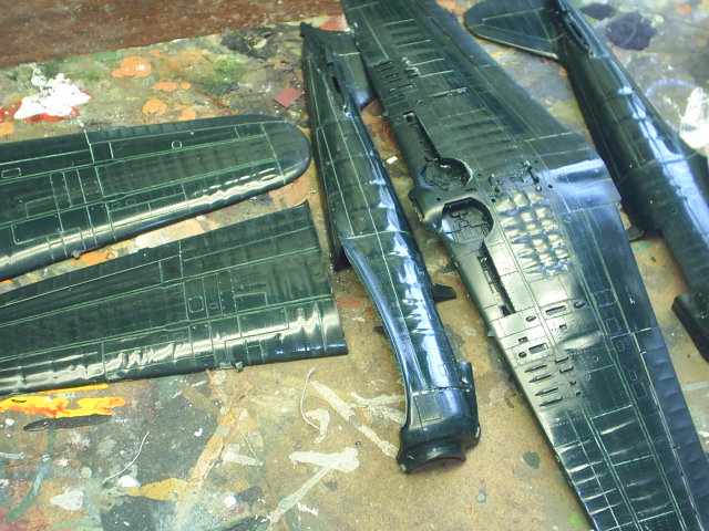
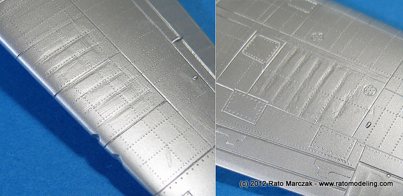
The previous steps may sound a little too much, but believe me, your eyes will trick you. If you don't follow the polishing steps, you may end up with this:
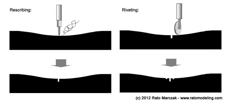
You can rescribe the model at this point, since it always call for some further sanding. I usually do the riveting at this stage too, as the next step will subdue it somewhat, and I personally don't like rivet lines standing visible like black dots. That's unrealistic.
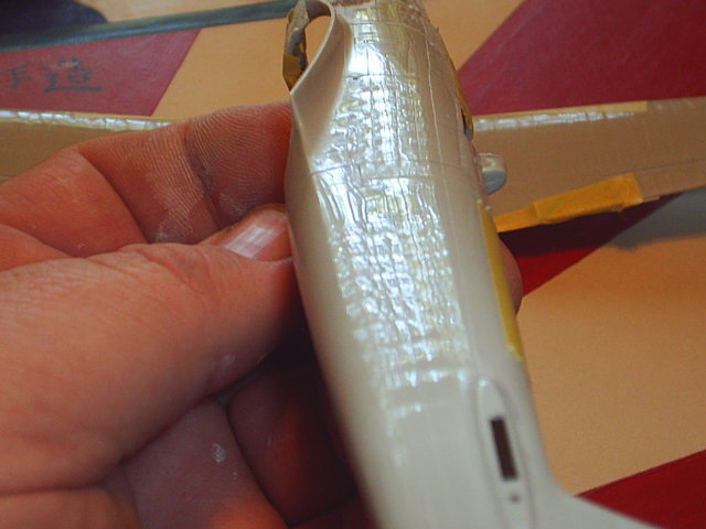
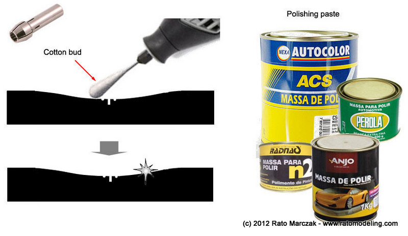
By then you will have your panel very smooth. If you are going to camouflage your model, you could stop here. But for a natural metal finished model, you need more. The next polishing step aims to remove the finest scratches - those barely visible on plastic, but that will show up once you shoot Alclad over it. For that I suggest you to cut a cotton bud in two halves, install it on your rotary tool dampened in your favorite polishing compound. I like to use polishing paste for automotive use. Remember, you want a nice surface, but this is not a scratched canopy:
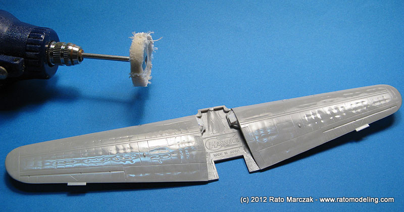
Another step - for those wanting a shiny natural metal finish - will leave a surface similar to the original part. Use a cotton disk (don't use the felt type!) to make the part gloss. It takes a few minutes, only, and it is worth the extra work. Here is my sample after the treatment:
Next, I use India ink spread liberally over the treated surface, let it dry, and remove it with an old shirt tightly wrapped around my finger. This leaves ink on the recessed areas, allowing you to check your results. In general, I don't use the method on the lower wings, but I do on selected areas of the fuselage, depending on the subject.
After a coat of primer, the part is ready for painting:
And that's it. It is time consuming, but I doubt manufacturers will include the effect in their products soon (yes, I know a couple of kits with the stressed skin effect molded on). Not all modelers like it. On the other hand, two or three nights of extra work will add a great deal of realism to your model, and remember, this is not something you can replicate with paint...
Anyway, I hope you find this article helpful.
Rato
Marczak
© 2012A bit of engineering
Take a look at those marvelous cutaway drawings:
What they have in common? They are cramped with structural details. In order to understand what stressed skin is, let's start by talking about these structural details. As you know, any aircraft structure is essentially a skeleton covered by a skin (pretty much like those balsa wood models). The skeleton parts are generally spars, ribs and stringers. These structural elements provide strength against bending and tensile loads, but almost no resistence to shear. If one would use spars and ribs only, and still aim a shear strenght, the weight of the resulting design would be prohibitively large. That's where the skin comes into play.
The skin is not only a thin metal sheet riveted along the ribs and stringers. It must be pre-stressed - or at least tightly fixed in place, which means that the riveting holes are calculated to be drilled along lines slightly smaller than the corresponding ones along the stringers and ribs. As a result, the skin must be somewhat stretched to fit its place. When you do this to all panels of a wing or fuselage, the skin is pre-stressed, just like a guitar string (or, in our balsa wood models, why we dope the skin - to make it tight). The result is a much more strong structure than the one which would be obtained if the skin wasn't pre-stressed. Not all panels in an aircraft are pre-stressed, but you can bet no panel is loosely fixed. Because it is so thin, without the pre-stress it will only add weight and no additional strentgh to the structures. So much so that fuselages don't have spars, they are only stringers, ribs and skin...
Therefore, the stringers, the ribs and occasionally the spars are the areas along which the skin panes are riveted. It is not difficult to identify them in an aircraft cut-a-way drawing. Check out this B-17 drawing. The arrows are showing areas that have rivet lines.
Now, what is the stressed skin effect, afterall? It is a representation on a scale model of the loosening of a skin panel due to use and loads. In order to unerstand it better, take a look of the wing center section drawing of a F4U Corsair, from the erection manual:
You can see several types of stringers (on the right) and the skin riveted to them. Here is a simpler version:
At this point it is important to understand that the wing (or any other structural part) sustain forces (lift, landings, manouvers) during operation. In the present case, bending is an example of forces acting on the structure. The lifting loads tend to bend the wing upwards. This produces a compression of the upper wing panels and a traction on the lower wing panels. Since the compression strength of the skin is minimal, it may buckle outwards, making a bubble on the area inside each panel lines perimeter (buckling is - stricktly speaking - not necessarily what happens here, so the term is used in a loose way):
The effect may happen with a few panels, or several consecutive panels. It all depends on each particular aircraft design. After the load is decreased to normal levels, it is expected that the skin will return to its flat shape. However, after hundreds of repetitive actions, small permanent deformations will occur, either on the skin, on the rivets, or on the surrounding structures, preventing the skin of returning to its original shape. Please understand that this is absolutely normal to some extent, and a buckled panel not necessarily means it failed. Do not confuse this with heavily deformed skin found on badly repaired areas, or heavily wrinkled panels found in restored (non flyable) warbirds which always tend to use the most possible original parts. It is also worth to note that manufacturing processes play an inportant role here, and many aircraft leave the factory already showing the effect. I mean, riveting process itself can (and generally do) produce the effect as the rivet lines pull the skin against the ribs and stringers, leaving sequences of bulges that is readily visible.
However, if the skin panel is no longer stretched as originally designed due to use (it has losen with time), then it is no more a pre-stressed structure as desired. That's why I mentioned that stressed skin is a bad name for it. I've seen modelers calling it quilted effect or oil canning effect. I'd rather prefer these names...
Here are some photos showing the effect on actual aircraft. The Corsair had a number of buckled panels on the area below the cockpit. This can be found in several wartime photos, like this one:
This B-25 is brand new at North American plant, yet the effect is visible under the cockpit:
Another interesting example is the Typhoon prototype, with the riveting lines quite visible under the wing:
The Sea Stallion and the Stratofortress are two pathological examples of modern aircraft with buckled panels. The Sea Stallion show the effect on both fuselage sides adjacent to the rear ramp, while the early B-52s had the front fuselage full of sheared panels (look under the "air" of U.S. Air Force marking):
I don't like to use restored warbirds as examples, but if they are flyable, faulty panels would not be allowed, they are better illustrations of the effect than B&W wartiime photos:
There are other technicalities involved, but I won't enter in such details. You've got the picture.
Get ready
So, where to start reproducing the effect on your model? If you want a short path, the panel lines are certainly a good start, but you must remember that panel lines, as the name says, are the lines delimiting the perimeter of the skin panels. Along with them, there are several other rivet lines inside each skin panel. If we look at a cross section spanning several ribs, what you see is the following:
Therefore, to be accurate you will benefit of good quality drawings of you aircraft. These plans help you to know where the rivet lines should go, besides the panel lines. There are several publications (Kagero, Koku-fan, Model Art, Design with Precision, among others) known for publishing reliable engineering plans, and several others not so (watch out with those drawings where the rivets are merely decorative features added by the artist). Do your homework. Here are two examples I used for a 1/72 Kawasaki Ki-61 project:
Then you have basically two options to depict the effect on your model: (a) you may add material (dissolved putty, Mr.Surfacer and the likes) between the rivet lines, to make it bulged. The difficulty of this method is to sand the borders of the puttied area to make it blend flush with the plastic. This approach was used by some famous modelers, including master modeler Robert Karr on his 1/32 Blenheim:
The other option is (b) to remove material along the rivet lines to make the non-worked areas to stand slightly higher. This is the preferred method of most modelers, but it also has its disavantages. You loose the panel lines, which must be rescribed later, and may not be able to avoid damaging other surface details. This is the method preferred by several modelers, Brian Criner, Bill Cronk, Jaroslav Galler, among others. Here are a couple of photos showing their work with this method:
We are going to show the second approach on this article. The series of photos below show models from several modelers, and help to illustrate how the effect can add realism to a model, particularly the ones in natural metal finish:
Basic steps
Now that you got here, let's put it simple: our aim is to produce more or less parallel waves over specific areas. As an example, lets remove material along panel lines molded in the original kit part::
Note that the panel lines may disappear completely or partially, so that a rescribing job will be necessary at the end. To make thing simple (to me), I'll illustrate the basic steps to produce one deression along a panel line:
Start doing some research. You don't want (you shouldn't) to make the effect over the whole airframe. Study photos of the real thing. Select the areas which are more prone to show the effect and take notes, if possible with the aid of a reliable drawing. Once you're done, mark the areas to be worked using a pencil or a sharpie (watch out, clean it afterwards) over the parts:
Once you stabilished where the depressions go, the first thing to do is to remove material quickly. In 1/48 or 1/32 scale, a curved hobby knife can be used as a srapper. It is important to be a curved tool, or you will produce risks difficult to remove later. Start lightly and then increase the force, but do not exaggerate - a few passes are enough.
You certainly will develop your own feeling with practice. In some cases, special tools may work better. I have a plastic scrapper specially devided for this:
At this point you will feel that you just scrapped (no pum intended) your latest model. Don't give up. Next, papare pieces of sandpaper, tightly rolled to fit the scrap marks you just did. I recommed to start with a 400 grade and then move to a 600 grade. Sand the marks with the rolls aligned to them. The objective of this step is to remove the steps (another unintentional pum) left by your scrapper - the ridge and beach marks highlighted in the figure above.
The rolled sandpaper will not enter into the smallest risks. In order to improve the smoothing, you can use an abrasive rubber dental bit. This is used by dentists to polish dental prothesis. Look for it, there are several types and brands on the market and they are useful for many tasks in modeling. Alternatively, you can punch out disks of 800 grade sandpaper and adapt them to your rotary tool. I like to use those sponge backed sandpapers for that, but you still can do it manually, but it takes a long, boring time...
The previous steps may sound a little too much, but believe me, your eyes will trick you. If you don't follow the polishing steps, you may end up with this:
You can rescribe the model at this point, since it always call for some further sanding. I usually do the riveting at this stage too, as the next step will subdue it somewhat, and I personally don't like rivet lines standing visible like black dots. That's unrealistic.
By then you will have your panel very smooth. If you are going to camouflage your model, you could stop here. But for a natural metal finished model, you need more. The next polishing step aims to remove the finest scratches - those barely visible on plastic, but that will show up once you shoot Alclad over it. For that I suggest you to cut a cotton bud in two halves, install it on your rotary tool dampened in your favorite polishing compound. I like to use polishing paste for automotive use. Remember, you want a nice surface, but this is not a scratched canopy:
Another step - for those wanting a shiny natural metal finish - will leave a surface similar to the original part. Use a cotton disk (don't use the felt type!) to make the part gloss. It takes a few minutes, only, and it is worth the extra work. Here is my sample after the treatment:
Next, I use India ink spread liberally over the treated surface, let it dry, and remove it with an old shirt tightly wrapped around my finger. This leaves ink on the recessed areas, allowing you to check your results. In general, I don't use the method on the lower wings, but I do on selected areas of the fuselage, depending on the subject.
After a coat of primer, the part is ready for painting:
And that's it. It is time consuming, but I doubt manufacturers will include the effect in their products soon (yes, I know a couple of kits with the stressed skin effect molded on). Not all modelers like it. On the other hand, two or three nights of extra work will add a great deal of realism to your model, and remember, this is not something you can replicate with paint...
Anyway, I hope you find this article helpful.
